
VoStack: Building a Four-Screen Dashboard from USB Touchscreens
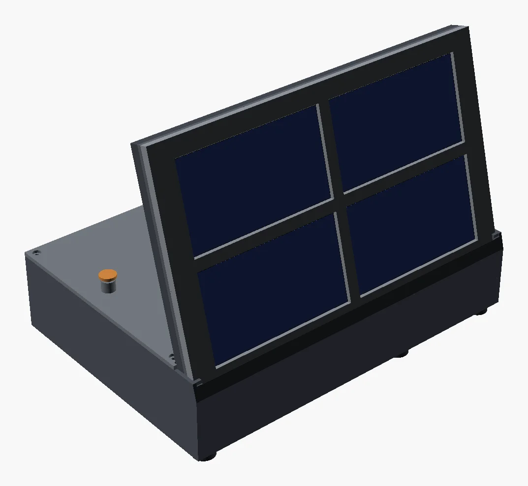
VoStack is a small box that sits on my desk: four 5” touchscreens in a 2×2 wall, leaning back on a printed stand, with a powered USB hub and a Raspberry Pi hidden in the base. It shows a clock and the weather, live stats from every machine in my homelab, what’s playing on Jellyfin, and a few touch controls. The plan is one power lead, a network connection, and nothing else.
The screens aren’t new. I bought them about four years ago for my sim rig, to build a custom display for it: a dashboard with gears, car info and the like. I got as far as an initial build, never built any more, and they’ve sat in a box ever since because I didn’t know what I wanted them for. A homelab dashboard turned out to be the answer.
The software and enclosure work started a week ago (6 October), and it’s been one of the most enjoyable projects I’ve done in a while, because it touches everything: a USB protocol, rendering, data from the homelab, and a 3D-printed enclosure with real tolerances. It also taught me a lesson about hardware that sits in a box for four years, which I’ll come to.
The screens
The panels are VoCore MPRO-5s: 5” IPS, 480×854 native portrait, capacitive touch, and powered over a single USB lead at about 1.35 W each. They’re cheap, bright and a sensible size for a dashboard tile. In landscape, each one is 854×480, and four of them make a wall a bit over 26 cm wide.
I had some old Windows code that drove one of these screens, from my Elite Dangerous project. But that code was Windows-only, and this needed to run on Linux, eventually on a Pi.
VoCore do publish a Linux DRM driver, which exposes the screen as a normal display. I didn’t want four tiny monitors joining my desktop, though. I wanted one program that owns all four screens and draws exactly what it wants on each. So VoStack talks to them directly from user space with libusb, and VoCore’s driver became the protocol reference.
Talking to the screens
The driver is C# on .NET 9, with libusb through P/Invoke. Each screen has one vendor-specific interface: a bulk endpoint for pixels and an interrupt endpoint for touch. Commands are vendor control transfers: wake the panel, tell it a frame is coming, then stream the frame as RGB565.
Most of it was straightforward. A few things were not:
- The panel is 854 rows, not 800. Send an 800-row frame and you get garbage. It’s a 5” variant with a taller panel than the rest of the range.
- The firmware shifts the image. Every frame came out offset and wrapped round the edge. The fix is to rotate the whole pixel buffer by a fixed amount before sending it. Rotating each row separately leaves a 1 px step. The old Windows code used a shift of 325; on these screens it’s 320 plus one row. I measured it with a calibration card that draws a border round the screen and adjusted it until the border was even all round.
- No serial numbers. Every screen reports the same USB IDs and no serial, so you can’t tell them apart from USB alone. There is a query for an 8-byte hardware UID, but the reply starts with a status byte. Forget to skip it and every UID is shifted by one byte, which looks stable and completely plausible until you compare two screens.
- Touch arrives as 14-byte reports in an FT5x06-style layout, in native portrait coordinates, which then have to be rotated into the same landscape space the page is drawn in.
On top of that sits ScreenSurface: a landscape SkiaSharp canvas that converts to the panel’s native layout, handles the firmware offset and an optional 180° flip, and skips sending frames that haven’t changed. Over USB 2.0 a full frame is 820 KB, so not sending the same clock face twice matters.
The dashboard
Pages are built from SkiaSharp widgets, and each screen shows one page. You swipe left or right on a screen to change it. There are five pages so far.
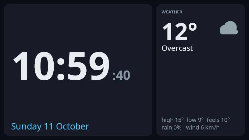
Time: a big clock and today’s weather from Open-Meteo, which needs no API key.
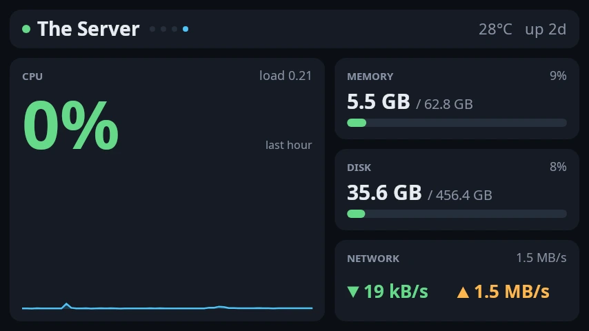
Machines: stats from Beszel, which already monitors every machine in my homelab. VoStack logs in to its PocketBase API as a read-only user and rotates through the machines every 30 seconds, showing CPU over the last hour, memory, disk, network and temperature. If a machine is down, it shows when it was last seen.
Media: when someone is playing something on Jellyfin, it shows the poster, the show and episode, progress, and buttons for that session. Otherwise it falls back to whatever is playing on the desktop.
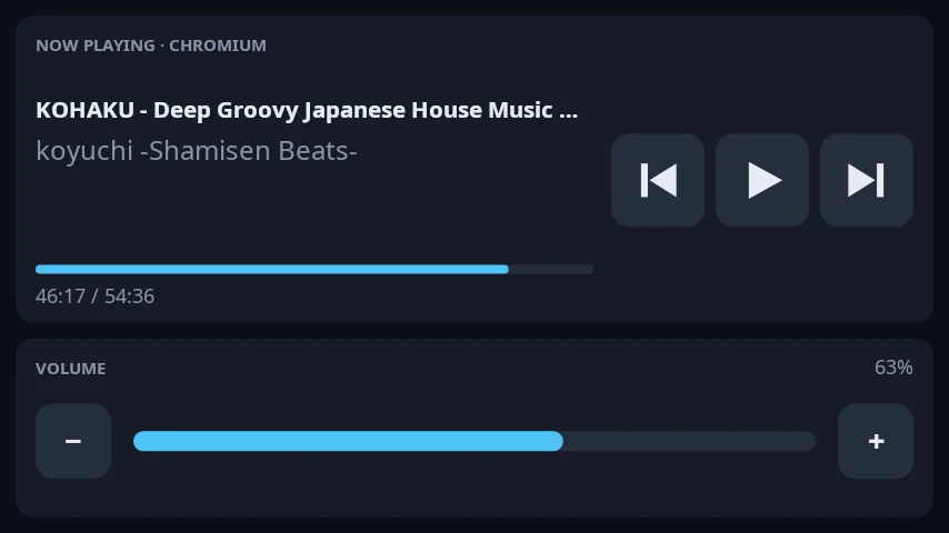
Stats and controls read the local desktop: CPU, GPU, memory and network, plus volume and media buttons. They’re left over from building it on my PC, and they’ll make less sense once it runs on the Pi.
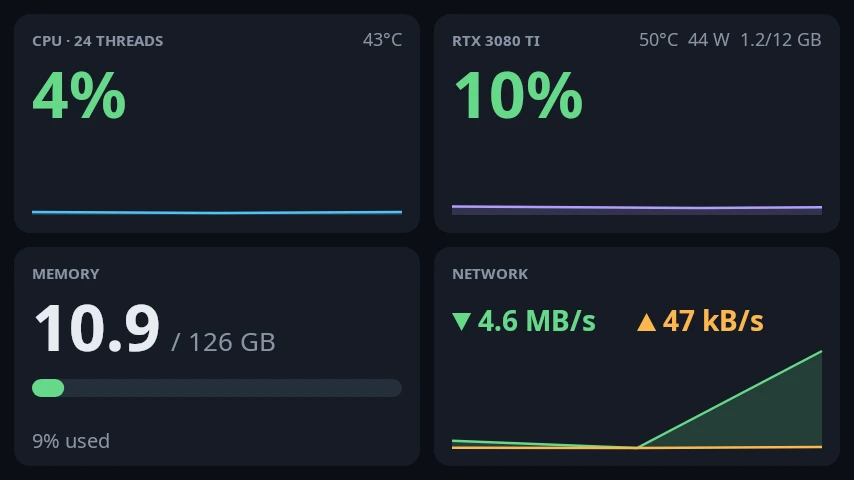
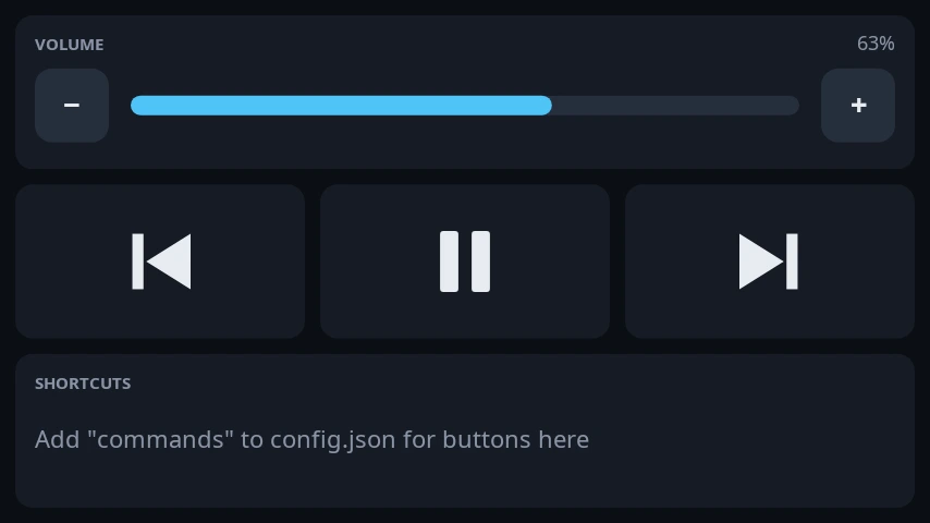
The config is a JSON file that reloads when you save it, so changing the screen order or a page doesn’t need a restart. There’s also a preview command that renders every page to PNG without any screens attached, which is how the images above were made.
The enclosure
This is where most of the week went. The whole thing is one parametric OpenSCAD file, with every measurement as a variable at the top, so a fit test that comes out half a millimetre wrong is a one-line change.
The face plate holds four sheets of glass with 10 mm between the windows. The windows aren’t centred on the glass, because the panel’s border isn’t even: 7.68 mm at the ribbon end, 2 mm at the other, 3.53 mm top and bottom. Each window sits over the actual picture. My printer is an Ender-3 Pro with a 220 mm bed, so the face is two identical halves, joined down the middle with filament dowels and glue. The right half is the same part rotated 180°, which means the ribbon ends face outwards and the right-hand screens are the other way up from the left ones.
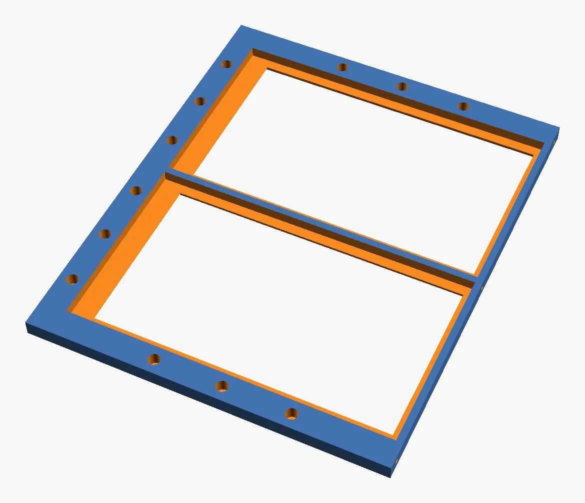
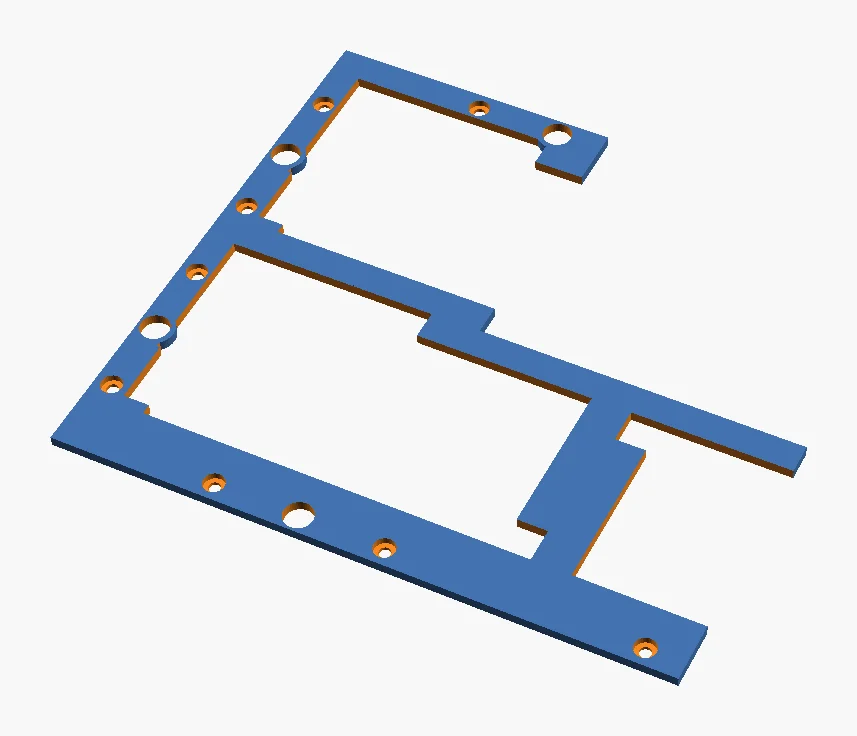
Clamp rings screw in from behind into heat-set inserts and hold the glass against a 2 mm lip, with foam tape so it isn’t clamped hard. They have a cut-out for the driver board, which folds behind each panel, and a notch for the touch flex. The joints are stepped: the clamps and the rear shells don’t split on the same line as the face, so each one screws into both halves and holds the glued seam together.
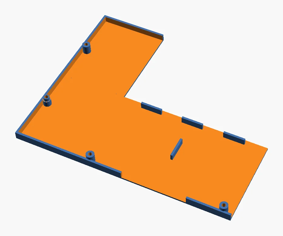
The base holds a TP-Link UH720 powered hub lying flat, with the Pi on a shelf above it. The screen panel stands on a ledge at the front and leans back 15°, held by side cheeks and trapped by the lid. The hub’s power button switches the whole box, so a printed pin goes through the lid down onto the button. It has vents in the floor and back, a hole for the 12 V lead, and feet to lift the floor vents off the desk. It’s split in two to fit the bed too.
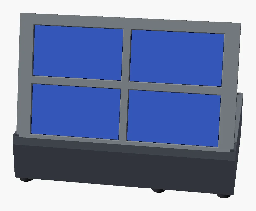
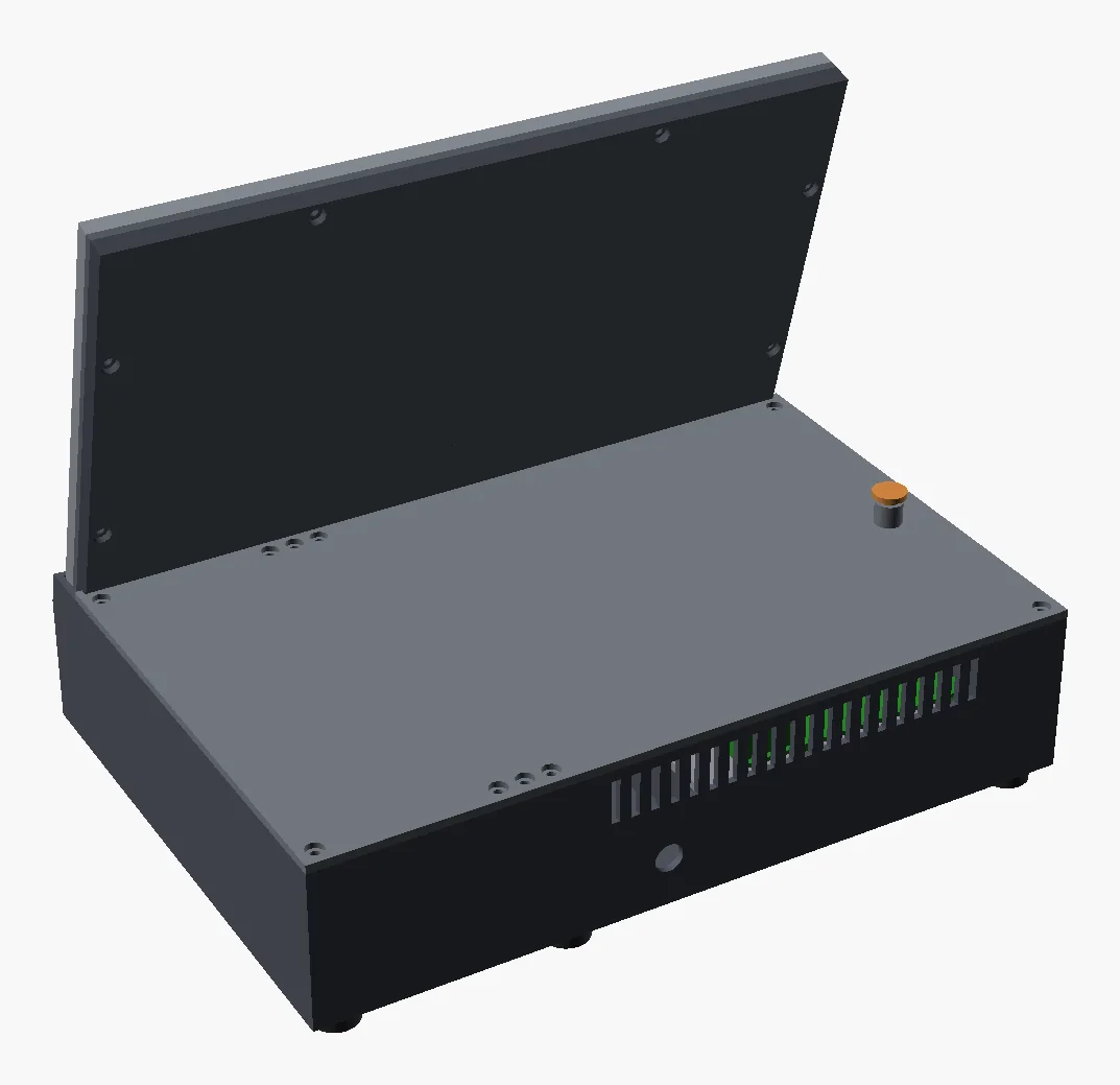
I did small fit tests before every big print: one window section to check the glass, then a ring and template to check the hub. The first glass test was wrong. The second was perfect, and that’s the one the face plate was printed from, in glow-in-the-dark PLA.
Putting it together, and losing half the screens
Last night all four screens went on the hub for the first time. The first job was working out which screen was which and which way up each one was. VoStack already had an identify command: it shows a big ? on every screen and you tap them in order. I extended it so you tap each screen near its physical top edge. If the tap lands in what the software thinks is the bottom half, that screen is upside down and gets flipped. One pass sets both the order and the rotation.
That’s when the problem showed up. One screen had vertical banding across half the panel. Reseating the ribbon didn’t help, so I added a pattern command that cycles solid colours, 1 px lines, a checkerboard and gradients. The banding was there on every pattern.
So I tried a spare screen. It was banding too. A third, it turned out, I’d cracked a while ago and forgotten about. Out of six screens, three were bad.
The last test was the useful one. I moved the driver board from the cracked screen onto one of the banding panels. The banding stayed, so it’s the panels, not the boards. It also showed me something I hadn’t expected: the hardware UID belongs to the driver board, not the panel. Swap the board and the “screen” gets a new identity. Good to know when the config is keyed on that UID.
Having sat in a box for four years, I had no way of knowing when they’d failed. That leaves three working screens, a few spare driver boards, and a replacement 5” on order. In those four years VoCore have moved the boards from micro-USB to USB-C. I already have the micro-USB leads, so the plan is to put one of my spare micro-USB boards on the new panel. Checking it with pattern comes first now, for every screen, before it goes anywhere near the clamp ring.
Working with Claude
Like the Cam Link Pro driver, this was built with Claude, in Claude Code. Every commit in the repo is co-authored. Claude wrote most of the code, the OpenSCAD model and the protocol notes, and it was quick: the driver, the dashboard and the first enclosure design were all in the first day’s commits.
What I brought was the hardware. Claude can’t see the screen. It can’t tell that the border on the calibration card is even, that a fit test is a hair too tight, or that the banding is still there after a reseat. A lot of this project was a loop of: Claude changes something, I look at the result, I describe what I see, it adjusts. The physical side (measuring the hub, printing fit tests, swapping driver boards) is still mine. That’s the same split I described in my post on being language agnostic: the tool handles the syntax and the boilerplate, and I bring the judgement about whether the result is right.
What’s next
- The fourth screen. Fit the replacement, test it, run
identify. - Move it to the Pi. Run VoStack in Docker on a Raspberry Pi 3B+ inside the base, deployed through Portainer like the rest of my homelab stack. The stats and controls pages read the desktop, so they need replacing with something that makes sense on the Pi.
- Print the rest. The clamps, shells and base, then heat-set inserts and glue.
- A 7.8” strip. VoCore also make a 7.8” 1280×400 screen. With a lower pixel density it’s almost exactly the same height as the 5” panels, just about 1.7 times as wide, so it could sit above or below the wall as a ticker. It needs its own page layouts, which is the fun part.
I’ll write a follow-up when the full box is assembled and running on the Pi.